Editor's Note: The miner's lamp is mainly used in coal mines, coal mines and underground working places. Because of the special working environment requirements, it is absolutely safe. Therefore, the design of miner's lamp is very important for safety considerations. The National Coal Mine Safety Committee has made some standards and requirements for the safety of miner's lamps, including: 1) In the design of the miner's lamp, all voltages must be less than 8V, including the input voltage, output voltage and the intermediate voltage required for the conversion. 2) The lamp of the miner's lamp must be the main and the second group, and it is completely independent control.
The main lamp is used for lighting applications most of the time, so the main lamp requires a large current and a long time of no less than 11 hours. The auxiliary lamp is mainly used for auxiliary work when the main lamp is not working. The current is generally small and the working time is long, not less than 30 hours. 3) The special application environment requires that all control circuits can not generate arcs or sparks during operation to avoid gas explosion.
Since miner's lamps are used in some special industries and environments, the following must be noted when designing miner's lamps:
In recent years, lithium-ion batteries have developed rapidly, and compared with traditional lead-acid batteries, lithium-ion batteries have advantages in volume and capacity, which makes most of the current miner's lamp production and design manufacturers use lithium-ion batteries as the power source for miner's lamps. Since the voltage range of a lithium ion battery is 3.6V to 4.2V, only a single lithium ion battery can be used as the energy source for the miner's lamp. A battery pack containing multiple batteries will exceed the 8V required by the miner's lamp, and conventional inductive boost circuits and capacitive boost circuits are not allowed.
Since the miner's lamp has two main and two sets and is independently controlled, the control modes of the two can not interfere with each other. More importantly, the control circuit must have high efficiency in order to meet long-term work requirements.
In order to avoid arcing or sparking at high voltages, the control switch is required to be connected to the ground instead of being connected to the power line to avoid arcing or sparking due to the switch.
The SP7611A is one of Sipex's low dropout series LED drivers that is quite different from traditional LED drivers. The traditional LED driver is based on a capacitive boost circuit or an inductive boost circuit. The voltage of the battery needs to be boosted to illuminate the LED. The SP761X is a sink-based LED driver, as shown in Figure 1. The voltage of the battery is greater than or equal to the sum of the Vf of the LED and the voltage of the cathode of the LED lamp to the ground, VLED, and the current flowing through the LED is constant. Due to the fierce competition of LED suppliers and the improvement of LED technology, the Vf of LEDs is getting smaller and smaller, from the original 3.5V~3.8V to the current 3.2V~3.4V. The range of VLEDs is 0.3V~1V. Therefore, in the lithium-ion battery 3.6V ~ 4.2V voltage range to select low Vf LED can meet the constant current drive.

Figure 1: The SP761X is a sink-based, step-down LED driver.
   This article discusses two application circuits for the SP7611A on a miner's lamp. The circuit of Figure 2 does not use the traditional inductor and capacitor as the boost, but directly drives the miner's lamp through the battery, thus effectively avoiding the radiation interference caused by the inductor. In addition, the circuit uses a linear power solution to avoid conducted interference due to the use of a switched-mode power supply. The circuit also avoids the possibility of arcing or sparking due to control of the power line by controlling the switches on the ground.
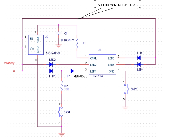
Figure 2: Application circuit for controlling the primary and secondary LED lamps of a miner's lamp with only one SP7611A
When SW1 is turned on and SW2 is closed, the main lamp output LED1~LED4 of the miner's lamp is lit. When the LED cathode to ground voltage V LED <=300m V, the current I LED flowing through LED1 = 200 × (V CONTROL - V CTRL ) / R1; when the LED cathode to ground voltage V LED >= 500m V, I LED = 435 × (V CONTROL - V CTRL ) / R1.
Where 200, 435 are the amplification of the current, as can be seen from the above equation, the current flowing through LED1 is equal to the current flowing through R1 multiplied by a magnification. This magnification has a lot to do with the V LED (Figure 3).
Through Figure 3, it can be simply summarized as a proportional relationship as shown in the table.

Figure 3: The relationship between the current amplification factor of the circuit of Figure 2 and the V LED voltage.
Of course, the current flowing through other LEDs is that the current flowing through LED1 is a mirror current, and they are equal and matched, and the matching degree of the current is 0.8%, and the maximum error is not more than 3%, as shown in FIG.
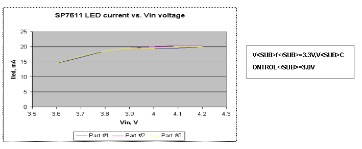
Figure 4: a current flowing through the other LED and V in voltage relationship.
Figure 5 is an efficiency curve of the actual test. The efficiency of this power scheme is E = 100 × (V battery - V LED ) / V battery . The relationship between efficiency and V LED and V battery can be seen from Figure 5. When the battery voltage is equal to 3.6V, the efficiency is as high as 91%; when the battery voltage is equal to 4.2V, the efficiency is also 79%, which is much larger than the traditional capacitive boost circuit (charge pump). The program's working time is greater than 11 hours.

Figure 5: Actual test SP7611A efficiency curve.
In the circuit of Figure 2, when SW1 is turned off and SW2 is turned on, the secondary LED lamp operates, and the current flowing through LED1, I LED = (V battery - V f ) / R2, where D1 is used to prevent current from flowing through the chip to ground. At this time, the chip SP7611A does not work, and since the current flowing through the LED 1 is small, the working time can be more than 30 hours.
Figure 6 shows another application circuit for the SP7611A, which uses two SP7611A to control the main and sub lamps, where U1 controls the main lamp and U3 controls the sub lamp.

Figure 6: Application circuit for controlling the main lamp of the miner's lamp by two SP7611A, respectively, where U1 controls the main lamp and U3 controls the sub lamp.
When SW1 and SW2 are closed, both U1 and U3 work, and the main lamps LED1~LED5 are lit. At this time, the LDO SPX5205 provides 3V power to set the current of LED1.
ILED1=Current Ratio×(VCONTROL-VCTRL)/R1
Where R1=R2.
When SW1 is turned on and SW2 is closed, U1 does not work, U3 works, at this time, the sub lamp LED5 lights up, and the current flowing through LED5 is:
LLED5=Current Ratio×(VCONTROL-VCTRL)/R2,
The Current Ratio here is the same as in Figure 2. It is worth noting that LED5 must be connected to pin 3 of U3 when U3 is operating. The current at pin 3 is in a certain magnification relationship with the current flowing through R2. If LED 5 is connected to another pin, this current is uncontrolled.

Table: Relationship between current amplification factor and V LED .
The SP7611A is a model of the Sipex SP761X series that can drive up to four LEDs simultaneously. If you want to drive a design with less than 4 LEDs, you can choose SP7612A, SP7614A, which can drive 3 LEDs and 2 LEDs respectively, similar to the design circuit diagram. The SP761X solves the problem of miner's lamp safely and cost-effectively with its 91% efficiency, small SC-70 package, direct drive LED without inductor or capacitor boost, and 0.8% current matching. Design problem.
Editor: China Lighting Network Liu Li
Led Display,Led Screen,Led Display Screen,led monitor
Guangzhou Chengwen Photoelectric Technology co.,ltd , https://www.cwledpanel.com