Due to the existence of the commutator during the speed regulation of the DC traction motor, its power and capacity are limited, and it is difficult to meet the requirements of high speed and heavy load of the electric locomotive. The AC traction motor has no commutator and insulated windings, so the structure is simple and
This article refers to the address: http://
Reliable, single unit power, capacity up to 1 600 kW. The transmission system of the locomotive has DC drive upgraded to AC drive, which meets the requirements of railway speed increase and heavy load traction, and is also the main development form of locomotive electric drive.
1 HXD3 electric locomotive traction characteristics
The HXD3 electric locomotive is controlled by constant traction and quasi-constant speed characteristics. Short-term constant traction control can achieve great starting traction. Quasi-constant speed control will reduce the traction of the locomotive according to the constant speed relationship (linear relationship). When the locomotive speed reaches the continuous speed, it enters the constant power control stage, and the constant power zone is located in the high speed section of the locomotive running, which can fully utilize the traction ability of the locomotive in the high speed section.
2 HXD3 electric locomotive traction converter
The traction converter is the core of the AC drive system of the locomotive, and provides VVVF three-phase AC power for the AC traction motor. In the AC-DC-AC drive system, the traction converter is mainly composed of a four-quadrant pulse rectifier (40C), a DC intermediate link (DC-Link) and an inverter (PWM). A typical two-level traction converter circuit is shown in Figure 1.
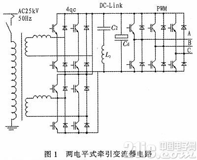
The power-side converter adopts a four-quadrant pulse rectifier to form an AC-DC converter. The PWM chopper control method is beneficial to improve the locomotive power factor and reduce harmonic interference.
The intermediate DC link is the supporting capacitor and the secondary filtering step. The voltage type converter has small torque ripple and small reaction force to the power grid, and is suitable for a high-power trunk locomotive. Therefore, such systems are commonly used in mains AC drive electric locomotives.
The motor side uses a three-phase PWM inverter to form a direct-interchange portion.
Mathematical Modeling of 3 HXD3 Electric Locomotive Traction Converter
1) Four-quadrant rectifier simulation circuit for HXD3 locomotive
Rated input voltage: Ud=1 450 VAC, input power: 50 Hz, output DC voltage: 2 800 V, transformer leakage inductance: LN=3 mH, secondary filter coefficient: C2=3mF, L2=0.84 mH, supporting capacitor: Cd = 8 mH. Using the 230bt algorithm, the transient DC control strategy.
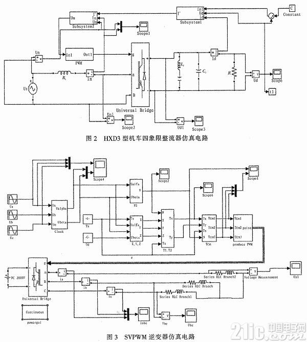
HXD3 locomotive four-quadrant rectifier simulation circuit, as shown in Figure 2, the simulation system includes three modules. Module one is a voltage outer loop controller, which is a constant voltage controller, generally adopting a PI controller. Module 2 is the transient current inner loop controller, which makes the system dynamic response and can quickly adjust the parameter changes. The PWM module is a PWM signal generator that is generated by comparing a triangular wave with a modulated wave.
2) Two-level inverter PWM mathematical modeling
The mathematical model of the SVPWM inverter uses open loop control, as shown in Figure 3. The three-phase inverter input rated DC voltage Udc=2 800V, SVPWM switching period Ts=0.000 2 s, input three-phase sinusoidal voltage Ua, Ub, Uc amplitude is 100 V.
4 HXD3 electric locomotive AC drive system simulation
1) Four-quadrant rectifier simulation analysis
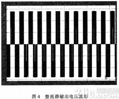
It can be seen from the simulation diagram 4 that the rectifier output rated voltage is 2 800 A, which basically meets the requirements of the rated operation of the four-quadrant rectifier of the HXD3 locomotive. And through the transient DC control strategy, by adjusting the reference DC voltage, the purpose of adjusting the output voltage and current can be achieved.
It can be seen from the simulation diagram 5 that the output voltage of the DC side of the four-quadrant rectifier contains many low-order and high-order harmonics.
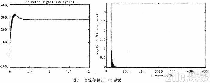
The generation mechanism of low-order harmonics, the DC-side output voltage contains twice the ripple of the grid frequency, and the obtained grid-side current setting value, which must contain the 3rd harmonic. When the actual grid-side current tracks the given grid-side current, the actual grid-side current will have a large 3rd harmonic, and so on, which will inevitably generate odd harmonics such as 7, 9, and 11.
The generation mechanism of higher harmonics, because the switching frequency is much higher than the modulation wave frequency, the grid side current changes to 5 times in one switching cycle, and the current only contains odd harmonics. Since the carrier ratio N=25, the higher harmonics are mainly distributed at 43, 45, 47, 49 times, and the like. Figure 5 verifies the correctness of the above analysis.
2) Two-level inverter SVPWM simulation analysis
This simulation takes a triangular wave with a frequency of 6 000 Hz, as shown in Figure 6. It can be seen in the spectrum that the harmonics are mainly distributed around an integral multiple of the carrier frequency. The main harmonic frequencies contained in the graph are much higher than the fundamental frequency and are easily filtered out.
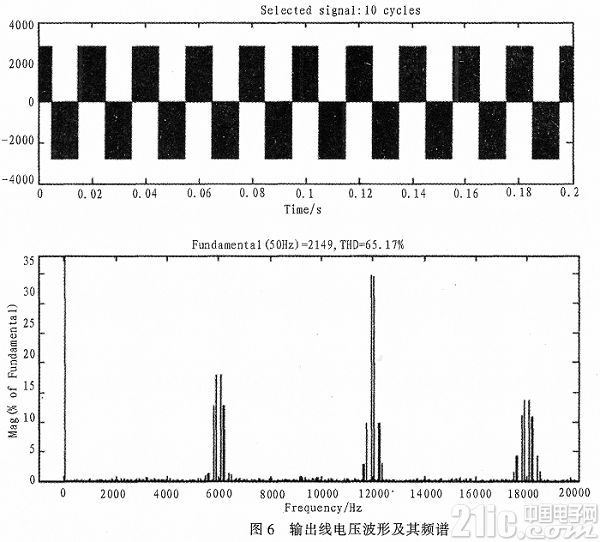
The higher the carrier frequency, the higher the harmonic frequency in the waveform and the smaller the volume of the required filter. Therefore, in order to eliminate the influence of higher harmonics, it is only necessary to increase the carrier frequency to filter through the filter.
5 Conclusion
This paper focuses on the AC drive system of the HXD3 electric locomotive, namely the traction converter part. Through the simulation analysis of the four-quadrant rectifier and inverter, compared with the parameters of the HXD3 locomotive in actual operating state, it is concluded that the harmonics of the output line voltage of the two-level traction converter are mainly distributed in the carrier frequency of the integral multiple. In the vicinity, it is verified that the four-quadrant rectifier contains only odd harmonics in addition to 2 times the power frequency, and the inverter only contains higher harmonics. At the same time, it is easier to filter out the harmonics of the part by increasing the carrier frequency. .
Led Flood light also known as the spotlight. it is able to aim in any direction and has a structure unaffected by climatic conditions.
It is mainly used for large area operation field, building outline, stadium, overpass, monument, park and flower bed, etc. Therefore, almost all large area lighting lamps used outdoors can be regarded as projection lamps.
The Angle of the outgoing beam of the projection lamp varies from wide to narrow, and the range of variation is 0°~180°, among which the beam of the particularly narrow beam is called the searchlight.
Flood Lamp,Projector Lights,Led Flood Lights,Outdoor Led Flood Lights
Jilin Province Wanhe light Co.,Ltd , https://www.wanhelight.com